Spring washers are specifically designed to provide a compensating spring force and sustain a load or absorb a shock. Many design variations have evolved to best serve one or the other of these two basic functions or to optimize both functions in a single part within specific I.D./O.D. limits.
Two principle factors are at work that continually increase the requirement for spring washers:
- The continuing effort to down-size many end products, relative to both weight and cost, creates a need for small, multi-functioning assembly components, such as washers that support a load, span a hole, or both, while providing a compensating spring force.
- Automated assembly requires some “play” or tolerance in the “fit” of components. Spring tension is needed to compensate for these tolerances.
Recognizing these two broad areas of influence, it can be stated that the more common applications for spring washers are:
- To take up “play” in assemblies due to cumulative commercial tolerances.
- To compensate for small dimensional changes in assembled components.
- To eliminate end play or rattles.
- To maintain fastener tension or “tightness.”
- To compensate for expansion and contraction or cold flow of material.
- To absorb intermittent shock loads and function as working springs capable of providing controlled reaction under dynamic loads.
Quality
WCL assures product quality three ways:
- We are affiliated only with manufacturers having outstanding programs and reputations.
- We have made a major investment in our Quality Inspection program to monitor the conformance of incoming parts to customer specifications and needs. We qualify parts from our manufacturers and processors to assure that all specifications are met.
- We have developed a state-of-the-art control system to insure required lot traceability and certification on any part we sell.
Design Considerations
 I. LOAD AND DEFLECTION PERFORMANCE
Load and deflection are the key characteristics of a spring washer. How much will the washer deflect under a given load and at what point will it flatten.
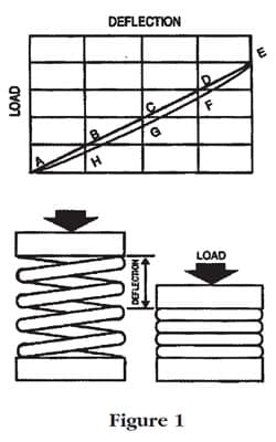
These values are normally shown in Load/Deflection (LD) curves with load, or applied force, measured on one axis and washer deflection on the other. A typical Load/Deflection curve for a simple coil spring is shown in Figure 1.
The spring depicted on the left, below the chart, is not deflected and there has been no load applied. On the chart we are at Point A. The vertical axis represents spring deflection in one-inch increments. The applications of 10 pounds of pressure deflects the spring one inch (Point B). The application of 20 pounds of pressure results in a two-inch deflection (Point C); 30 pounds, three inches (Point D); and 40 pounds, four inches (Point E). At this point, the spring is fully compressed. This graph reflects a linear curve, or “constant spring rate”, as each ten pounds of pressure produces one inch of deflection. Most spring washers do not perform this consistently.
As the force is gradually released, it is apparent that the spring does not return to the full extension it had before deflection. This is evident on the return at Points E, G and H. At Point E, for example, at a deflection of three inches, the spring is supplying a little less than 30 pounds of reactive force. This results from the spring having used some of its stored energy to overcome friction caused by the bearing surface at both ends. Some stored energy is also lost through the increased temperature that results from intermolecular friction caused by the initial deflection.
When considering washer design, there is an obvious relationship between washer thickness and load bearing characteristics. There is and inverse relationship between washer thickness and spring compensation or deflection. The physical design of washers can be varied to serve either or both of these basic performance characteristics.
- Single Wave Washers
These washers are designed for applications involving low loads and requiring high deflection. The Load/Deflection (L/D) curve for this type of washer is virtually linear. Applications include the take up of large tolerance variations, eliminating end play in electric motors, minimizing rattles and cushioning light loads.
- Multiple Wave Washers
These washers provide somewhat greater load bearing capacity than single wave washers with some loss in deflection capability. Multiple wave washers have wide application as take-up springs.
 Conical Washers
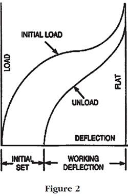
Conical washers can have either a solid periphery or a divided periphery. Conical washers with a solid periphery have exceptional load-bearing capacity but deflection capability is reduced and, with the exception of true Belleville type washer, they will take an initial set when loaded to flat. After initial load (and set), they will function elastically from the unloaded position to the flat loaded position (see Figure 2). As a general rule, maximum deflection for conical washer is approximately one-tenth of rim width.
Washers with scalloped peripheries provide added, and sometimes controlled, spring reaction or deflection with some loss in load bearing capability. Like solid periphery washers, divided periphery washer will take an initial set when loaded to flat.
For a complete review of performance characteristics on Belleville and Disc Spring washers, turn to our Disc Spring Washer section.
- Ramp Conical™ Washers
Shakeproof’s Ramp Conical washer has a unique, off-center parabolic ramp to create a secondary spring system that provides increased spring reaction and greater load-bearing capacity.
-
Square Cone® (Square Dome) Washers
Square Cone (Square Dome) Washers enhance both load and deflection. Two distinct conical configurations are combined in the washer to provide: 1) live spring action under full design loads; 2) greater control as a result of a longer deflection period; 3) controlled tension; 4) improved load distribution. Load is delivered toward the outer periphery of the washer, making it ideal for clamping fragile materials and for spanning large clearance holes.
-
Finger Washers
Fingers on the outer periphery of these conical shaped washers enhance their resiliency and permit even distribution of pressure away from the center hole. This type of washer is often used as a ball bearing retainer spring.
 Conical Washers
II. LOAD/DEFLECTION CALCULATIONS
When specifying a spring washer, functional and physical requirements must be carefully analyzed. In considering load requirements, two basic types (static and dynamic) must be recognized as well as the amount of load.
- Static Load
In a static load environment, the basic function of the spring washer is to retain load. In such an environment, the elastic load of the material may be exceeded.
 Dynamic Load
In a dynamic load environment, the washer functions as a regularly flexing spring and the elastic the material must not be exceeded. Loading the washer beyond its yield strength results in permanent distortion of the crown height.
The type and magnitude of the load to which a spring washer will be subjected and the reactive force it will be required to exert are the primary factors that determine the type of spring washer best suited to a specific application. This range of deflection, or “spring travel”, is an important element of spring washer design.
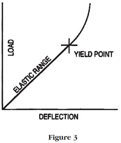
Values for maximum load and maximum deflection are shown for many of the wave washers listed. If these limits are exceeded, the washer will not operate within the elastic limits. (See Figure 3.) A general design rule is to select a washer that has twice the needed deflection, to avoid overstressing the washer.
Where values are not given, values shown for washers with similar I.D., O.D. and thickness dimensions provide am approximate indication of performance.
- Single Wave Washers
The load equation for a single wave washer is: P= S (D – d) t2 / D 6
The deflection equation for a single wave washer is: f= S D2 / 6 E tP = load(lbf)
E = modulus of elasticity of material (30,000,000 psi for steel)
t = material thickness (in.)
f = deflection (in.)
d = inside diameter (in.)
D = outside diameter (in.)
S = max. allowable stress (200,000 psi for steel)
Note:These equations are presented only to explain the values which are provided as a guide for the wave washers listed in this catalog. (Calculated values can vary up to 30% from actual values in some cases.) - Multiple Wave Washers
The load equation for a multiple wave washer is: P = S N2 t2(D – d) / .75 (D + d)
The deflection equation for a multiple wave washer is: f = S 2 D2 / 12 E t N2N = number of waves
P = load (lbf)
E = Modulus of elasticity of material (30,000,000 P.S.I. for steel)
t = material thickness (in.)
f = deflection (in.)
d = inside diameter (in.)
D = outside diameter (in.)
S = max. allowable stress (200,000 psi for steel)Calculations for conical Disc Spring washers are included in the Disc Spring Washer section.
- Single Wave Washers
 Dynamic Load
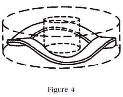 III. Space Envelope
Wave washers and conical washers increase just slightly in diameter as they are compressed. Allowable inside and outside diameter limits are, therefore, an important consideration when specifying spring washers. The overall space occupied by a spring washer can be described as a hollow “cylinder.” (See Figure 4). This “cylinder” of space must be recognized in assembly design considerations and restricts of the acceptable dimensions of the washer itself. Generally, the larger the washer O.D. that can be accommodated, the greater the load than can be supported and distributed.
IV. Environment
The environment in which a spring washer operates can effect the anticipated performance of the washer in terms of load bearing and reactive characteristics. Temperature and exposure to corrosive agents are the most important environmental considerations and washer material specifications must be made with these factors in mind.
The limitations imposed by even relevantly low ambient temperatures on various spring washer materials are provided here as a guide. These indicated temperature limits can, of course, be exceeded but this will result in increased relaxation of the washer under load.
| Material | Recommended Operating Limit Temperature F° |
|---|---|
| SAE 1050 Steel | 250° |
| SAE 1065 Steel | 250° |
| 425 Phosphor bronze | 225° |
| Beryllium copper | 225° |
| Spring brass | 150° |
V. Functional Variations
As performance requirements become more exacting, established formulas, which provide data for good theoretical design, may not be sufficiently precise in view of the many variables that are introduced in the commercial manufacturing process. Normal operating tolerances in stamping dies and material, normal tolerances in material thickness and composition, heat treatment, plating and finishing can result in variations in load-bearing characteristics in the magnitude of ±35%. Unfortunately, these variations are usually greater in the smaller sizes where specifications tend to be the most critical and where the basic design cannot accommodate much flexibility.
Today, the designer must determine what functional tolerances are acceptable so as to know whether commercial spring washers can be used in the application or whether a precision, calibrated spring washer is needed. If there is a question in this area,WCL engineers can provide valuable guidance in finding the best and most cost-effective component.
VI. Design Alternatives
In developing the proper spring washer for an application, the design engineer will want to recognize three alternatives:
- If general commercial tolerances are involved, a review of this Spring Washer catalog may be sufficient to identify a spring washer that will meet the functional needs of the application. If needs are not oversimplified and special aspects of the application, such as environment, are taken into consideration, this is the most straightforward and economical option.
- If the tolerances are precise within moderate range, the design engineer may use the formulas presented here to develop a specification range which can then be compared to the parts listed in this catalog. This can avoid the unnecessary cost that would be associated with development of a new design to function within parameters already served by an existing part.
- If tolerances are critical and performance requirements complex, the designer can determine the “space cylinder,” define the function and environment and review the design alternatives with a WCL representative.
Although listed last, the degree of precision and sophistication required by the application is the first criteria that must be determined as the design engineer evaluates available options.