Ideal when components are fastened from the opposite side of the panel. Snap-in grommet covers the screw point with an attractive, decorative head.
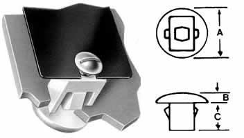
| PART NUMBER | TYPE | PANEL HOLE SIZE* | PANEL THICKNESS RANGE | SCREW SIZE | HEAD SIZE A |
HEAD HEIGHT B |
PRONG LENGTH C |
|---|---|---|---|---|---|---|---|
| 212-320602-01 | R | .250 x .343 | .040-.060 | 8 | .485-.515 | .085-.105 | .377-.397 |
| 212-320334-00 | R | .312 x .343 | .062-.092 | 8 | .485-.515 | .095-.105 | .505-.525 |
*See panel hole size recommendations below.
NOTE: Dimensions listed are nominal.
NOTE: Dimensions listed are nominal.
Test Data (Representative Samples)
| PART NUMBER | SCREW SIZE | DRIVING TORQUE† | STRIPPING TORQUE† |
|---|---|---|---|
| 242-160502-70 | 6 | 2-4 in.-lh. | 10-15 in.-lh. |
| 8 | 4-6 in.-lh. | 14-21 in.-lh. | |
| 242-170602-80 | 8 | 3-5 in.-lh. | 11-17 in.-lh. |
| 242-180602-90 | 8 | 3-5 in.-lh. | 10-18 in.-lh. |
| 10 | 5-8 in.-lh. | 16-28 in.-lh. | |
| 242-180602-91 | 8 | 4-6 in.-lh. | 13-21 in.-lh. |
| 10 | 6-9 in.-lh. | 20-30 in.-lh. |
| PART NUMBER | SCREW SIZE | DRIVING TORQUE† | STRIPPING TORQUE† |
|---|---|---|---|
| 242-180602-92 | 8 | 5-7 in.-lh. | 15-22 in.-lh. |
| 10 | 8-10 in.-lh. | 25-30 in.-lh. | |
| 242-180602-93 | 8 | 7-9 in.-lh. | 22-28 in.-lh. |
| 10 | 9-14 in.-lh. | 30-45 in.-lh. | |
| 242-210602-10 | 1/4″ | 12-17 in.-lh. | 30-45 in.-lh. |
*Note–When Installing Grommets:
- It is desirable that the burr side of the hole be opposite the grommet entry.
- The surface condition of the hole edge has a definite bearing on the ease with which a grommet can be inserted and how well it will fit and hold until the screw is driven. For instance, the smaller end of the hole size range, when used with a porcelainized surface, can provide a leak proof fit. Indicated hole sizes are final, i.e.: after painting, enameling, etc. For hole sizes that will provide the best combinations of easy installation and secure fit, the following can serve as a general guide:
Surface Condition Hole Size
Porcelain: Small end of indicated range
Enamel: Slightly below mid range
Paint: Middle of indicated range
Plastic Panel: Middle of indicated range
Raw Metal: Large end of indicated range
- Driving torque and stripping torque will generally increase with decreasing hole sizes and increasing panel thickness.
NOTE: †Driving and stripping torques will vary depending on panel hole size, panel thickness, and screw type used. In all cases, however, the stripping torque is at least 250% of the driving torque.
NOTE: Dimensions listed are nominal.
NOTE: Dimensions listed are nominal.